# I/O Board Installation
The i/o board comes in two different versions, one mounts 16 output relays and the other mounts 24 output relays. Ideally, it's enough to know how many connections you need to connect all the valves and parts of your washing machine to choose which version is best suited for your application. In any case, this documentation will see you through the entire installation process.
# Power supply input

| Connector ID | Pin | Pin Function |
|---|---|---|
| XM1 | 1 | +24v DC |
| 2 | Earth | |
| 3 | 0v |
# Power Supply Specifications
Voltage Range:
- from 18VDC to 34VDC
Power Consumption:
Maximum consumption:
- 24 relays version: 15W
- 16 relays version: 10.5W
Consumption in stand-by: 120mA @ 24VDC
# Modbus Connection
In the following table the modbus interconnection are detailed:
| Connector ID | Pin | Pin Function |
|---|---|---|
| XM6 | 1 | B - |
| 2 | A + | |
| 3 | Common/GND |
# Modbus address and function

The following table details the modbus interconnections. The switch selection allow to preset the modbus address between 0 and 4, based on the digital bit weight shown below. The modbus address has a factory preset value of 1: SW1-Bit#0 ON.
| Connector ID | Switch | Dip switch function |
|---|---|---|
| SW1 | 1 | Bit#0 address |
| 2 | Bit#1 address | |
| 3 | Bit#2 function(reserved) | |
| 4 | Bit#3 function(reserved) |
ATTENTION
The above dip-switch may be unavailable, because may be hardwired on some board version: in case they was available, pay attention to not modify the value preset at the delivery because they may affect the HERA kit functionality or even unallow the I/O board to work with the CPU panel.
# Relays Contact Specifications
- Resistive load: 10A - 250 VAC/30 VDC
- Maximum switch power: 2500 VAC
- Maximum switch voltage: 440VAC/300VDC
- Maximum switching current: 10A
- Maximum switching power: 2500VA/300W
# Coils Connections Bank #1
Here you can see the connection layout of the coil bank #1.
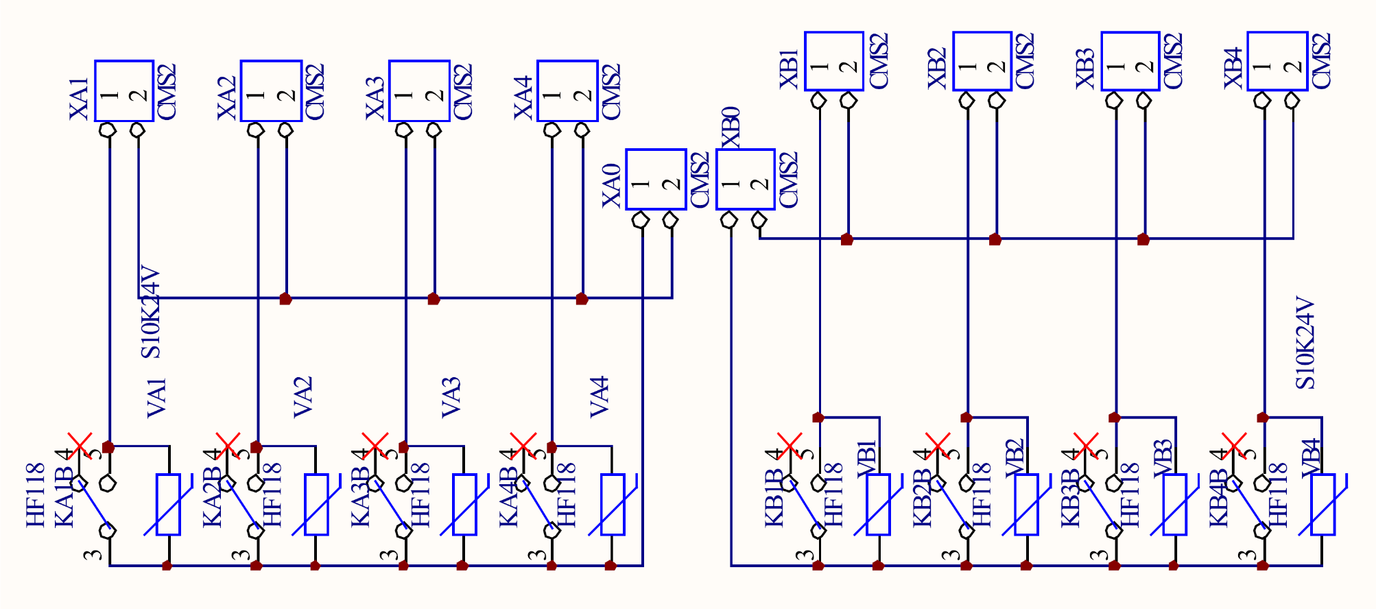
| MDB Coil ID | Connector ID | Pin Num | Pin Function |
|---|---|---|---|
| XA0 | 1 | Common rail pin#1 switched ‘XA1-4’ coils | |
| 2 | Common rail pin#2 ‘XA1-4’ coils | ||
| K1 | XA1 | 1 | CHEM_1 |
| 2 | CHEM_1 common | ||
| K2 | XA2 | 1 | CHEM_2 |
| 2 | CHEM_2 common | ||
| K3 | XA3 | 1 | CHEM_3 |
| 2 | CHEM_3 common | ||
| K4 | XA4 | 1 | CHEM_4 |
| 2 | CHEM_4 common | ||
| XB0 | 1 | Common rail pin#1 switched ‘XB1-4’ coils | |
| 2 | Common rail pin#2 ‘XB1-4’ coils | ||
| K5 | XB1 | 1 | SYS_AUX_1 |
| 2 | SYS_AUX_1 common | ||
| K6 | XB2 | 1 | INVERTER_BAL_ENB |
| 2 | INVERTER_BAL_ENB common | ||
| K7 | XB3 | 1 | INVERTER_DIR_REV |
| 2 | INVERTER_DIR_REV common | ||
| K8 | XB4 | 1 | INVERTER_DIR_FWD |
| 2 | INVERTER_DIR_FWD common |
# Coils Connections Bank #2
Here you can see the connection layout of the coil bank #2.
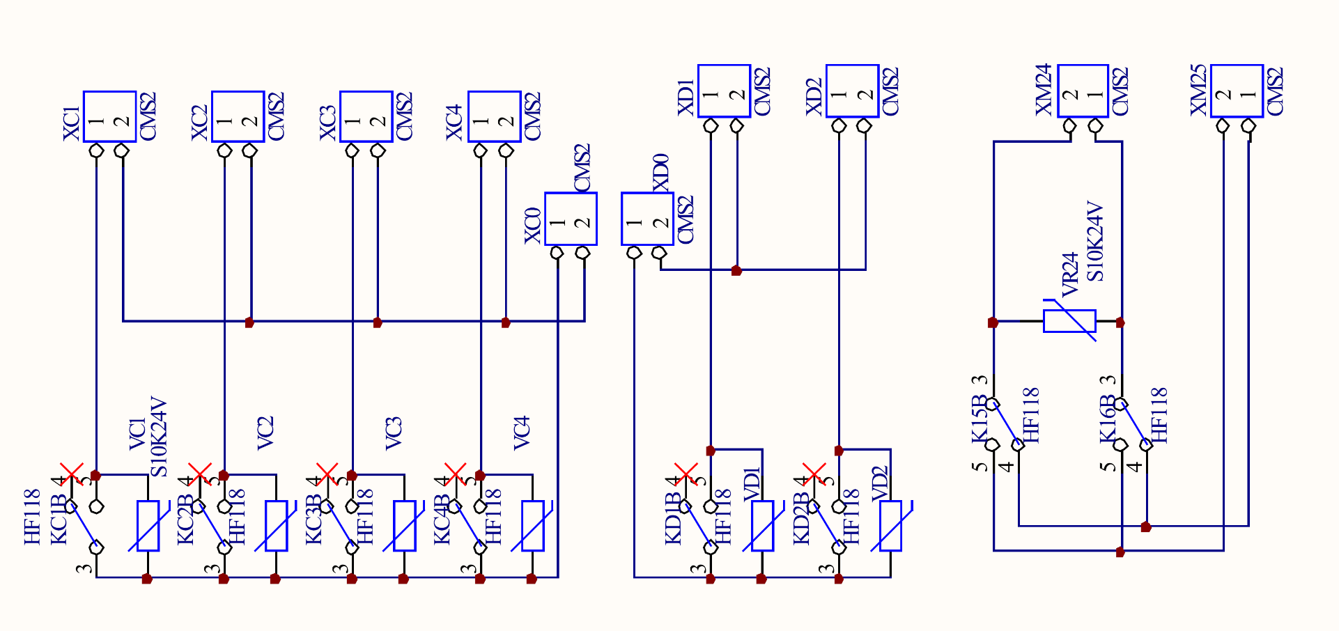
| MDB Coil ID | Connector ID | Pin Num | Pin Function |
|---|---|---|---|
| XC0 | 1 | Common rail pin#1 switched ‘XC1-4’ coils | |
| 2 | Common rail pin#2 ‘XC1-4’ coils | ||
| K9 | XC1 | 1 | HEATER |
| 2 | HEATER common | ||
| K10 | XC2 | 1 | AUX_TAP |
| 2 | AUX_TAP common | ||
| K11 | XC3 | 1 | HOT_TAP |
| 2 | HOT_TAP common | ||
| K12 | XC4 | 1 | COLD_TAP |
| 2 | COLD_TAP common | ||
| XD0 | 1 | Common rail pin#1 switched ‘XD1-2’ coils | |
| 2 | Common rail pin#2 ‘XD1-2’ coils | ||
| K13 | XD1 | 1 | DOOR_SAFE_LOCK |
| 2 | DOOR_SAFE_LOCK common | ||
| K14 | XD2 | 1 | OPEN_DOOR |
| 2 | OPEN_DOOR common | ||
| K15 | XM24 | 1 | DRAIN_OFF(-) DRAIN_CLOSE(-) DRAIN_OPEN(+) |
| K16 | 2 | DRAIN_OFF(-) DRAIN_CLOSE(+) DRAIN_OPEN(-) | |
| XM25 | 1 | DRAIN_IN_1 GND supply | |
| 2 | DRAIN_IN_2 +24VDC supply |
Note regarding XM24 and XM25
If Hera Laundry has the drain mode configured as no-timeout, the commands drain OPEN and drain CLOSE will be driven keeping indefinitely the voltage accross the rele outputs: the drain CLOSE command will match with the 'DRAIN_CLOSE' polarity in the table above, while drain OPEN will match with 'DRAIN_OFF' polarity. This drive configuration mode may be used for pneumatic valve. If the drain mode in configured as timed-out , a time configuration value shall be requested and the drain OPEN and drain CLOSE commands will result respectively in 'DRAIN_OPEN' and 'DRAIN_CLOSE' polarity of the table above, for the configured timeout, to support drain valves powered by DC motors .
# Optional(24 rele) Coils Connections Bank #3
Here you can see the connection layout of the coil bank #3. The following coils bank and the associated connector is available only for 24rele I/O board type.
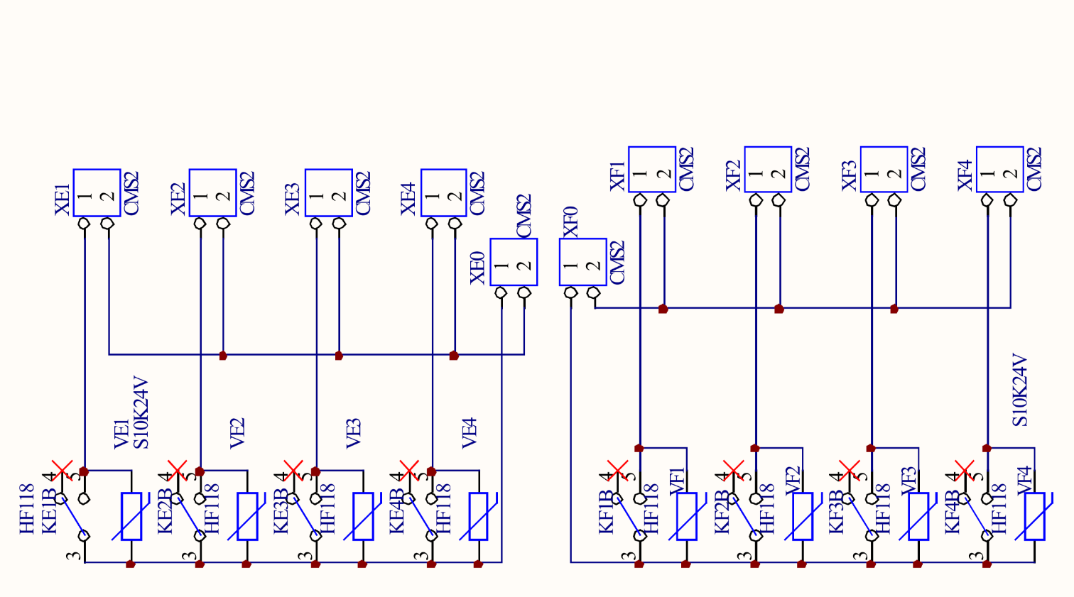
| MDB Coil ID | Connector ID | Pin Num | Pin Function |
|---|---|---|---|
| XE0 | 1 | Common rail pin#1 switched ‘XE1-4’ coils | |
| 2 | Common rail pin#2 ‘XE1-4’ coils | ||
| K17 | XE1 | 1 | AUX_3 |
| 2 | AUX_3 common | ||
| K18 | XE2 | 1 | AUX_4 |
| 2 | AUX_4 common | ||
| K19 | XE3 | 1 | AUX_5 |
| 2 | AUX_5 common | ||
| K20 | XE4 | 1 | AUX_6 |
| 2 | AUX_6 common | ||
| XF0 | 1 | Common rail pin#1 switched ‘XF1-4’ coils | |
| 2 | Common rail pin#2 ‘XF1-4’ coils | ||
| K21 | XF1 | 1 | AUX_7 |
| 2 | AUX_7 common | ||
| K22 | XF2 | 1 | AUX_8 |
| 2 | AUX_8 common | ||
| K23 | XF3 | 1 | AUX_9 |
| 2 | AUX_9 common | ||
| K24 | XF4 | 1 | AUX_10 |
| 2 | AUX_10 common |
# Digital Inputs Specifications
Voltage ranges:
- AC: from 9 to 27 VAC
- DC: from 12 to 34 VDC
# Digital Inputs Bank #1
Here below you find detailed the layout of the optoisolated digital inputs bank #1.
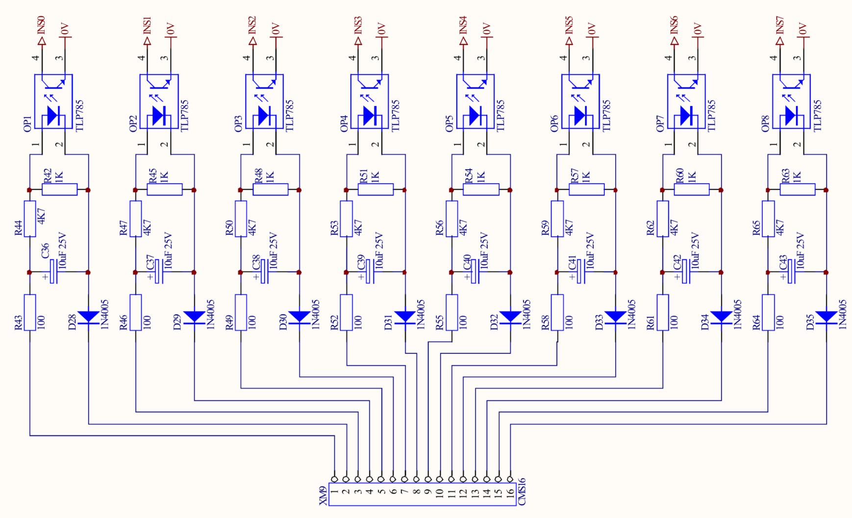
| MDB Digital In ID, bank #1 | Connect or ID | Pin Num | Pin Function | System Configuration option |
|---|---|---|---|---|
| IN S0 | XM9 | 1 | INVERTER_FAULT_IN pos | not-fitted or: fault = powered/unpowered |
| 2 | INVERTER_FAULT_IN neg | |||
| IN S1 | 3 | INVERTER_UNBAL_IN pos | not-fitted or: fault = powered/unpowered | |
| 4 | INVERTER_UNBAL_IN neg | |||
| IN S2 | 5 | DOOR_LOCKED_IN pos | not-fitted or: closed = powered/unpowered | |
| 6 | DOOR_LOCKED_IN neg | |||
| IN S3 | 7 | DOOR_CLOSED_IN pos | not-fitted or: closed = powered/unpowered | |
| 8 | DOOR_CLOSED_IN neg | |||
| IN S4 | 9 | MOTION_LIMIT_IN pos | not-fitted or: fault = powered/unpowered | |
| 10 | MOTION_LIMIT_IN neg | |||
| IN S5 | 11 | WATER_LEAKAGE_IN pos | not-fitted or: fault = powered/unpowered | |
| 12 | WATER_LEAKAGE_IN neg | |||
| IN S6 | 13 | SPARE_1_IN pos | ||
| 14 | SPARE_1_IN neg | |||
| IN S7 | 15 | SPARE_2_IN pos | ||
| 16 | SPARE_2_IN neg |
TIP
- The inputs are compliant to AC or DC voltages and are electrically independent between them. DC inputs shall be provided according to negative/positive polarity shown on the pinout description above.
- Any grouping between different provided inputs with different common voltage could be arranged and shall be hardwired.
# Pressure Sensor

Here below you can find the pressure sensor details:
| MDB Sensor ID | Pressure sensor device |
|---|---|
| Analog #0 | SG1 |
Comprehensive error (%FS):
- 1% FS
# Analog Outputs
Below the analog voltage and current outputs available on XM7 connector are detailed.

In the following table is the supplied analog outputs. The analog current output path may be powered thru a +15v available on XM7 pin #5 where the pin #6 shall be connected to any of the I/O board GND present on XM2/3/4 pin #3 .
The current and voltage INVERTER_SPEED below are both driven to provide the appropriate drive for the VFD.
| MODBUS id | Connector ID | Pin Num | Analog function | Pin Function |
|---|---|---|---|---|
| PWM #3 | XM7 | 1 | 0v ÷ 10v | |
| PWM #2 | 2 | 0v ÷ +10v | INVERTER_SPEED_V_CONTROL | |
| PWM #2 | 3 | -10v ÷ +10v | ||
| PWM #0 (@ PWM #1 == 0) | 4 | 4mA ÷ 20mA Current Sink input | INVERTER_SPEED_mA_CONTROL | |
| PWM #1 (@ PWM #0 == 0) | 4mA ÷ 12mA Current Sink input | |||
| 5 | (fused) +24v output | |||
| 6 | GND |
# Analog Outputs Specifications
Voltage output:
- minimum allowed load: 300 Ohm
Current output:
- maximum allowed load: 470 Ohm
Comprehensive error (%FS):
- 2% FS