# CPU Installation
The CPU enclosure contains the display, the electronic parts, and the connectors on the back side of the display. In order to provide the electrical installation of the CPU, the following connections shall be arranged:
- Power supply connection, on J4
- Modbus connection to the I/O board, on J2
The following image shows the back side of the CPU with its connectors and with pin #1 for J2 and J4.
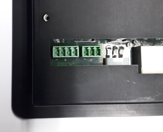 )
)
# 24vAC/DC Power Supply Connection
The CPU supply is compatible with AC or DC supply. The following is the J4 power supply connector layout
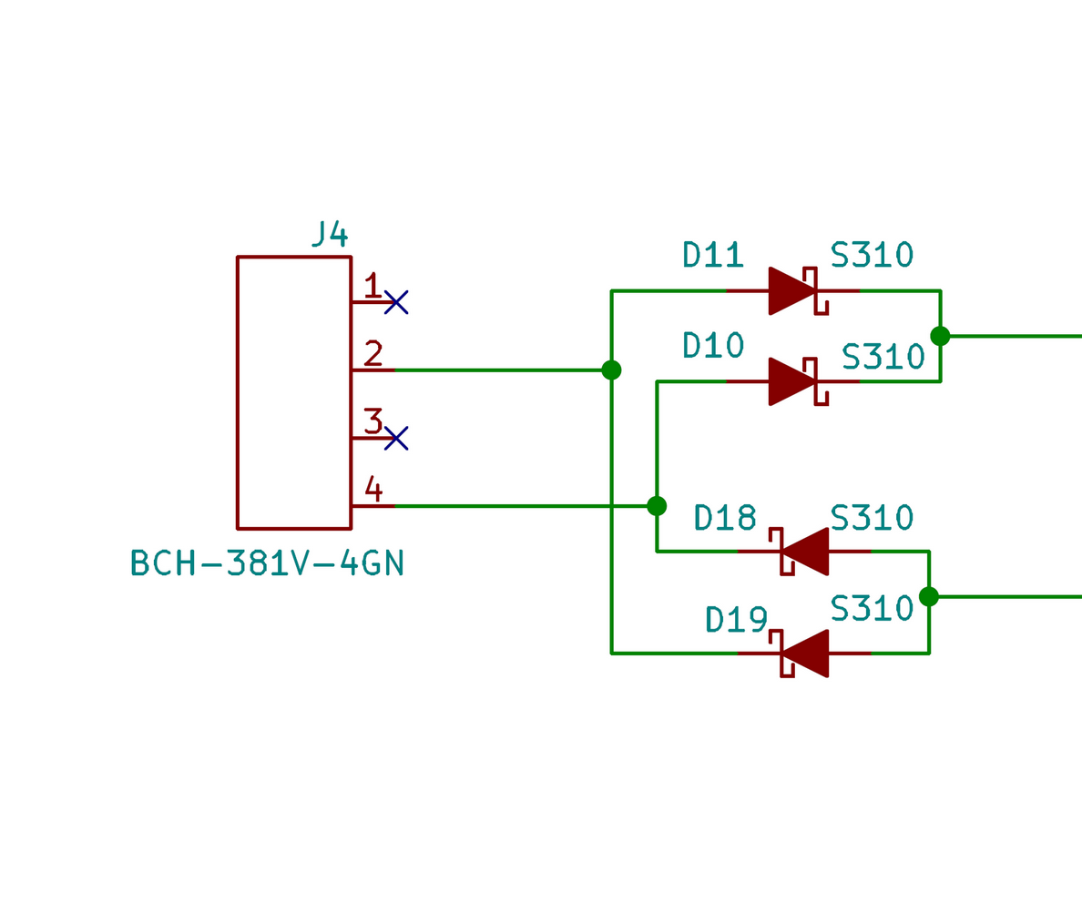
The following is the J4 power supply connector pinout
| Connector ID | Pin Num | Pin Function |
|---|---|---|
| J4 | 1 | n.c. |
| 2 | 24v AC/DC | |
| 3 | n.c. | |
| 4 | 24v AC/DC |
# Power Supply Specifications
Voltage:
- from 9 to 27 VAC
- from 12 to 34 VDC
Consumptions:
- Maximum consumption: 9W
- Consumption in stand-by: 310mA @ 24VDC
# Modbus Connection to the I/O board
The following is the J2 Modbus connection layout
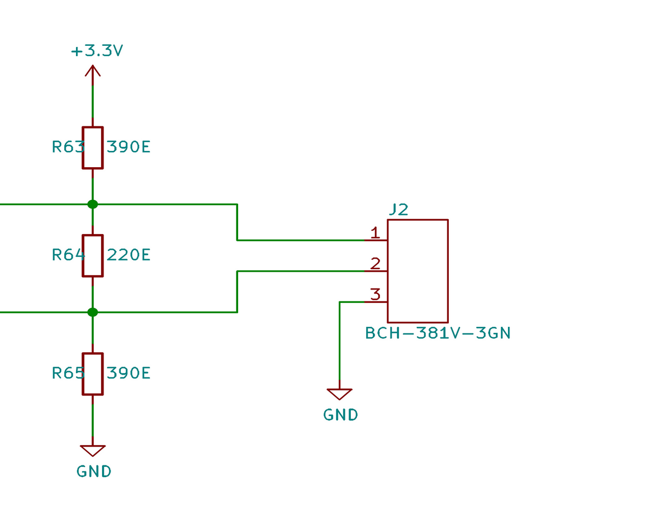
The following is the J2 Modbus connection pinout
| Connector ID | Pin Num | Pin Function |
|---|---|---|
| J2 | 1 | A+ |
| 2 | B- | |
| 3 | Common |
WARNING
The Modbus cable shall be made up of a twisted pair, 22-24 AWG, 120 ohm, for A+ and B- terminals, plus a single wire for common. The shield is optional and shall be connected only on one side between I/O board and CPU on the common/GND terminal.
ATTENTION
After you complete the installation of the CPU, you should proceed right away with setting up the system parameters. Machines should not be sent out to field with factory mode, with settings parameters available, on.